
How to build a Tamagotchi by Emiko P. '25
and the power of curiosity
This semester I built a Tamagotchi: a 2000s toy where the user takes care of a virtual pet! My Tamagotchi, fondly named Tamako, was like the fetus version of a full-fledged Tamagotchi—it was capable of walking, jumping, and looking oh-so-adorable.
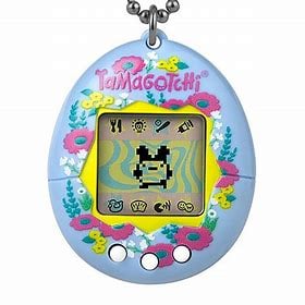
this is what the original Tamagotchi toy looks like
As a mechanical engineering major, I had never worked close enough with electronics to the point of designing them, and that had been something I’d really been wanting to remedy. Specifically, I wanted to learn how to design a circuit board.
And that’s where 2.679: Electromechanical Systems II comes in! I took this class for one main reason: the final project was a completely opened ended opportunity to design your own printed circuit board (PCB)! Once I heard that the class would be funding the project and had full access to an amazing course staff, including Steve Banzaert,01 an icon within the mechanical engineering department for not only being a whiz with anything electrical (or musical) but also for making it <i>interesting</i> , I was fully on board.
From the very beginning, I wanted to make something cute and fun. My mind kept circling back to retro video games—pixelated cartoons and satisfying, clunky buttons. I eventually landed on the idea of building a Tamagotchi because how fun is that??!
So, without further ado, here are the steps showing how you can build your very own Tamagotchi. (Also check out the end of this blog to see what others in this class created!)
Step 1: Design schematic and prototype
A schematic is a drawing of your electrical components and all of their connections to each other. This is where you decide what features you want your circuit board to have. The components I selected were a TFT LED display (the screen that would show my Tamako pet), three buttons, power switch, 9V battery, and Arduino Nano.
The hardest part of this was figuring out the proper configuration of my LED display to my Arduino Nano. There was very little documentation online about this display (because one of the TAs kindly scrounged around their lab to find a spare one for me), so I had to go through each pin manually and figure out what its function was and how it matched to the Nano.
I made sure to build a quick little prototype that verified this would function how I wanted it to. I had all of these parts already, but usually there would be another step of ordering your parts off of DigiKey, Adafruit, etc.
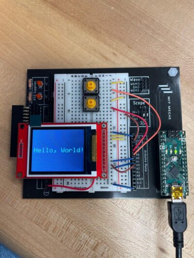
successful prototype
I was then able to translate this prototype to a schematic, which shows all of these components and their connections in a symbolic diagram.
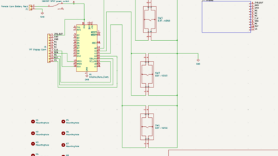
schematic
Step 2: Design PCB layout
This is the part where you bring your schematic to life. How will these connections and these components be positioned on your actual board? I had to keep in mind that I wanted this to be a playable, hand-held game: I was going for a clean look that optimized space.
After organizing the PCB on KiCad, I shipped off the design to be manufactured in China. This is what returned to me a week or so later!
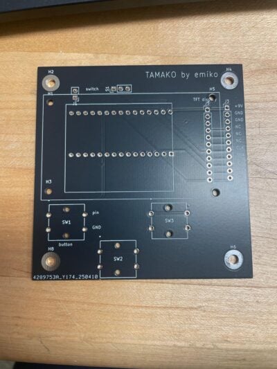
my very first printed circuit board! tamako has arrived :)
An important lesson I learned during this step was: ALWAYS MAKE SURE YOU SAVE YOUR WORK PROPERLY!!
Side story if you’re interested: I thought I was being careful with this, but right when I was about to submit my PCB for shipping after working on it for three hours in lab one day, I came back from a break to have realized the thing I had saved was the version of the PCB from the day before!
*cue freak out*
I told my professor, and he said my only hope was to go back to the same computer (which someone else was using at the time), and see if it was magically there.
“Until then, the best thing you can do for yourself is to take a walk.”
And that’s what I did. I speed-walked around the basement of Pappalardo, along the street of Mass Ave in a rage-induced haze, then returned after I’d finally cooled off and accepted that I was just going to have to redo the work.
Turns out, it was actually saved on that original computer (hallelujah). Lowkey anticlimactic story, but at the time I felt like I had literally been blessed. It all worked out in the end, but I learned some important lessons: 1) carefully save your stuff, 2) don’t underestimate the power of a good walk.
Step 3: Solder
This is the step where you physically join parts to the board by connecting their two metal surfaces together. I was pretty new to this skill, but it’s honestly a quick learn, especially because it’s obvious when you’ve made a really solid connection between the two joints.
This is what Tamako was looking like after I installed all the parts.
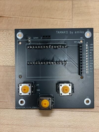
I placed the Nano on the back of the board to optimize space, and the screen isn’t on here yet because I made it removable. It connects to the black header on the far right.
Step 4: Verify PCB works
This step had one good thing and one bad thing. I’ll start with the bad: I had prototyped this board by displaying text, not images. Unfortunately, this means that I didn’t realize until after I received my PCB that I hadn’t made any way to electrically access the chip that could process/ store the images. TLDR: no images on screen unless I wanted to do some dramatic, complicated rewiring.
However, the good news is: THE PCB WORKED THE SAME AS THE PROTOTYPE!! This is actually huge. The amount of things that could have gone wrong are numerous: I could have messed up the connections between the display and the Arduino, the board could have magically decided it didn’t want to work, I could have done a poor soldering job so there were poor electrical contacts, etc.
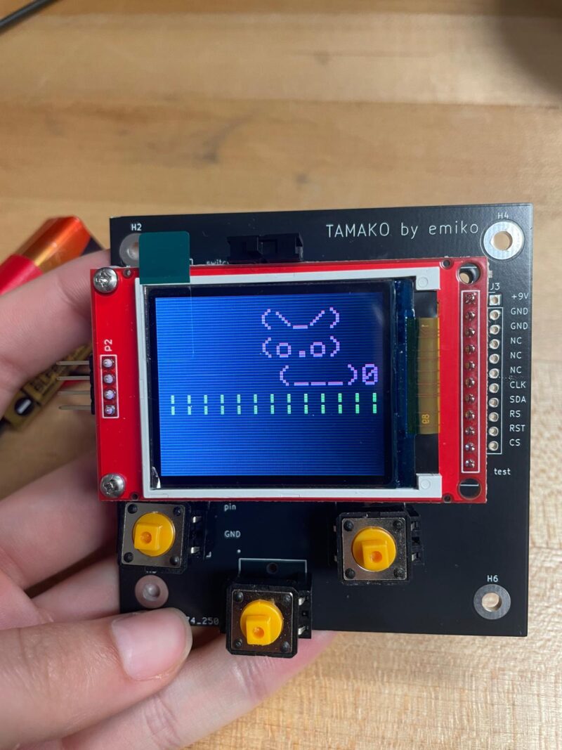
But, remarkably, it worked first try. That was huge! And once I realized that I could just form images out of text, I was pretty happy. So in the end, I would say this PCB definitely meets my expectations!
Step 5: Develop software
I knew that my minimum viable product (the bare bones criteria I would have to meet in order to consider this project a success) was a device that could have a little pet move around on the screen and jump. So that’s exactly what I did! I made the pet go left, right, and jump. It was perfect :)
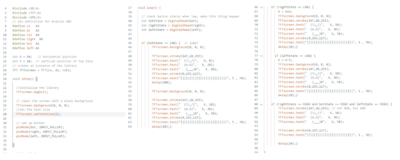
arduino code!
Step 6: Enjoy (and iterate!)
And with that, the Tamagotchi is complete! It’s pretty simple right now, but there is always room to code something more complicated, to 3D print a plastic shell, and to keep experimenting with the project. But when all is said and done, I’ve loved collecting practical experience with KiCad and Arduino, and I am so proud of myself for successfully designing a PCB for the first time. Learning is fun! Yay!
I hope you enjoy playing with your very own Tamagotchi :)

Curious what other people in my class made this semester? Let’s take a look.


This is part of the reason why I love MIT.
The final project was completely open-ended—everything people created here was fueled by their own imagination and whimsy. Many of these people had never really worked with electronics before, but they were willing to learn entirely new skills to bring their visions to life. I felt like I was watching my class dream: they wanted to create something, they were unsure if they possessed the skills to do so, and through some magical mixture of curiosity and drive—they did it. The dream came true.
I mean, what a powerful, crazy, utterly insane idea! To make things because we can! To let our imagination run wild and free, to not reel it back into the realm of the easy and manageable, but to chase it off into the distance and see where it takes us! To accept that we may fail in the pursuit of bringing our dream to life. To push ourselves not because of a class requirement, but because we must try. Because it is in our DNA.
Because this is what drew us to MIT in the first place: unapologetic, relentless curiosity—the secret sauce that makes the impossible possible.
- an icon within the mechanical engineering department for not only being a whiz with anything electrical (or musical) but also for making it interesting back to text ↑