[Guest Post] Designing the 2025 East Campus Rollercoaster by Aiden H. '28
by Zack I. ‘27
Intro
Every year, my dorm (East Campus) constructs a large-scale wooden build project to attract freshmen during orientation week. In the past, these projects have included multi-story fort structures (read my fort construction guest post from last year!), rollercoasters, ferris wheels, and other similar rides & attractions. All of our projects undergo a stringent design and approval process culminating in a review by a licensed City of Cambridge structural engineer to ensure they are safe enough to build. This process takes the better part of the year (or a full year for a project of this scope) as the design is iterated upon and improved until it is ready for construction. From September 2024 until its construction in August of 2025, I was the designer and project lead for the 2025 East Campus rollercoaster, our biggest and most ambitious project constructed thus far. There are about a hundred thousand things that could be said about this experience, but in this blogpost, I will be primarily focusing on how I designed this year’s rollercoaster.
Defining Goals & Constraints
East Campus has constructed wooden rollercoasters before (2005-2010, 2014, 2015, 2022), but those were all straight-line (2D) coasters. My biggest goal going into the project was to design and construct the first EC coaster with a banked curve. This had never been done before due to difficulties associated with bending wood into the shapes necessary for the track to curve around. Additionally, our rollercoasters are typically not designed with rider throughput or operative efficiency in mind, creating long lines and straining our volunteer operator staff. Creating a coaster that completes a full, connected loop would also dramatically improve the efficiency of our cart resetting process, allowing us to increase our throughput and meeting what I anticipated would be a high demand for rides. The other early new design feature that I selected was for this to be our first multi-rider coaster, settling on the cart having two riders. In addition to increasing efficiency, a multi-rider cart would allow the coaster to become a social experience, which I felt was significant given that it was a project constructed for freshman orientation weekend.
Simulating & Prototyping
As mentioned above, EC was under renovations and its future residents were living scattered throughout campus. The year before renovations, I was living in a former frat house across the river in Boston, and as a result I didn’t have a ton of room in my living space to prototype like I would have been able to in EC. Now that we are back in the building and have our own well-maintained makerspace, project leads going forwards will have the ability to do far more testing and prototyping than I could, which I highly recommend.
Most of the work on the coaster from September to December of 2024 was administrative, consisting of proposing the project’s concept to the various MIT stakeholders who would evaluate it for approval. Once I got the greenlight to pursue the fully engineered design based on my proposed safety features & procedures, I began seriously designing the coaster over winter break. There were a few sheets of ¼” plywood leftover from the 2024 fort sitting in my house’s basement, so I used them to conduct bending tests to determine if the track surface could even be shaped into a curve like I was envisioning. Intuition told me no, but once I actually began bending the sheets I found that they were actually quite flexible when bent along the grain. These bending tests convinced me that a wooden banked curve was possible and that was when I chose to completely commit to a banked curve.
I had access to a simple MATLAB script that the 2014 coaster had used to calculate the g-forces throughout their track and ensure that it was safe for human riders. I played with adapting it for a bit, but eventually decided it would make the most sense for me to just create my own script more custom to this year’s needs, which I chose to do in Python instead. The primary use of this script was to calculate a) that vertical & lateral g-forces were within a safe range for riders and b) that the cart would have enough energy to make it to the end of the track. This was mostly based on simple first-year physics (yayyy banked curve problems are real), but required me to make some assumptions about the friction between the cart and the track that were difficult to fully validate and be confident in. However, this was what I used to lock down the conceptual structure of the track (initial drop height, approximate banked curve radius, number of inclines and drops later on, etc.). My initial script only spit out text output, but for our design presentation later on Spruce C. ‘26 wrote a more detailed and better parameterized simulation (with nice-looking graphics too) that can be played with here.
CAD & Structural Design
I split the track into four main types: the tower, the straightaways, the curves, and the transitions between the straightaways and curves. I divided the track up into regions based on when it switched between these types.
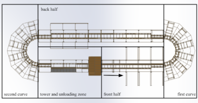
The regions of the coaster track. In order: tower, front half straightaway, first curve, back half straightaway, second curve, and the unloading zone straightaway connecting back to the tower.
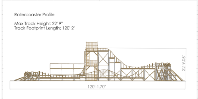
Some dimensions of the coaster to provide a bit more context lol.
Curves
I began with the curves because I anticipated them being the most challenging thing for me to work out. Early on while I was trying to work out how to avoid bending the plywood multidirectionally, Hanu S. ‘26 suggested that I cut the plywood into trapezoids to approximate the turn of the curve. This ended up being the suggestion that fully convinced me that a banked curve with our construction methods would be possible because up to that point I was still skeptical about how the plywood would respond to stress along multiple axes simultaneously. When it came to figuring out how to support those trapezoids, I went through at least 6 separate design concepts from start to finish until I landed on one that actually worked. My problem was that initially I was thinking about my design from a top-down approach, attempting to fill in the support structure going from the plywood sheets down to the ground. However, this led to designs that had too many gaps at the ground and intermediate levels to be strong enough (especially since our loads were ~twice as much this year with the two-rider cart). Eventually, I threw it all out and began from the ground up instead and that yielded a much better result.
I decided to split it up into 6 repeating units that would allow the track to curve the full 180 degrees around. I chose 6 units because that would divide the angular displacement of each unit into even 30 degree increments. I decided to make my footprint trapezoids too to allow everything to fit flush together, creating a much more stable foundation than in previous iterations. The exact lengths of the supports were based on the typical approximate lengths that 2x4s are sold in to reduce construction time and the number of cuts required during assembly. The first and the second curve segments of the track were essentially the same structure to reduce complexity with the only difference being the height of the supporting stilts below them. This ended up being a huge plus during construction because it allowed me to build one curve unit as an example and have others copy it exactly to construct the rest of the curve, reducing the amount I had to directly supervise.
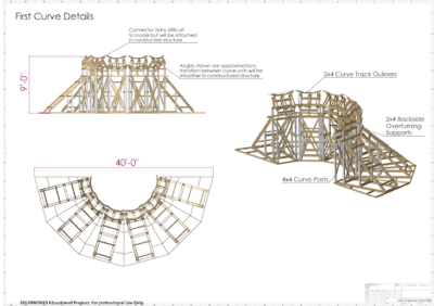
Dimensioned drawing of the full curve structure (plywood omitted for clarity).
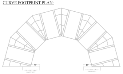
Plan drawing of the curve’s footprint from our construction documentation.
Straightaways
I focused on the curves the most and did not spend as much time as I should have designing the straightaways. The straightaway structure I designed was split into two main sections: the scaffolding substructure and the track superstructure.
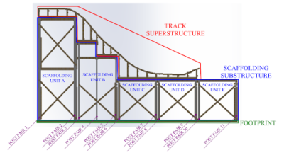
Components of a segment of straightaway labeled.
The substructure consists of large box “units” with 8’ x 8’ square footprints and varying heights based on the track’s necessary height at that point. Having such a simple and repeatable structure made the scaffolding super easy and quick to construct. Giving every unit the same regular, square footprint also made it easy to survey the build and ensure that everything fit together once constructed.
The superstructure was formed by columns of varying elevations that matched the rough elevation of the track at specific points. Then, angled 2x4s called track outliners were attached to the columns. These outliners were screwed in with only one screw at first, giving everything a necessary degree of freedom to be adjusted into a smooth curve. Once all the outliners were attached at appropriate angles to create our continuous track profile, the additional screws constraining everything were put in. This allowed us to make easy, quick adjustments to the angles of the track which made it easy to construct smooth inclines and curves.
Tower
In the past, East Campus has implemented 8’x8’ “fort units” and used them to construct the majority of our forts and other static platform structures. These fort units are standardized square platforms that EC has extensive experience and transfer of knowledge regarding how they are built, which makes it easy for us to utilize them every year. However, building an 8’x8’ tower that would provide me with the 22 ft of height that I needed for the initial drop would be extremely unstable. Additionally, because the cart was now designed to seat two people, it was substantially wider and meant that there would be less room on top for the operator and participants to comfortably board and initiate the ride. As a result, I decided to increase the tower footprint to 12’x8’ and had to size up many members (from 2x8s to 2x12s) to support our increased load. I initially designed our tower to have plywood shear walls to further increase its stability, but the wind load calculations found that the walls created too much surface area and I had to remove them to get the final approval from the structural engineer.
Transitions
The transitions were by far the most complex and difficult part of the project and were also the part of the design that I was the least happy with once it came time to construct it. I chose to do this by having approximately 10 “ribs” that would change in elevation and angle gradually throughout the transition to connect the curves and the straightaways.
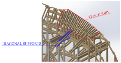
Labeled components of the transition between curve and straightaway.
This design seemed fine on paper, but to construct it was actually a nightmare. Estimating the angles and heights to create a smooth transition that also matched the curve to straightaway start and end points was time consuming and largely inaccurate. The ribs were too densely packed to fit an impact/drill in between them and adjust them once built, so the entire rib had to be removed, re-estimated, and then reinstalled to fiddle with the height or angle in any way. To be fair, this could have been mitigated if I built the transitions before the straightaways. Then, I could have just matched the straightaways to the transitions (instead of the opposite) which would have been much easier. But producing a design that would be easier to adjust during construction would still have saved a lot of time on what ended up being the biggest roadblock to quick progress during construction.
Documentation
The CAD model and design of the coaster was only a fraction of the work actually required to make this project happen. In order to be granted a construction permit by the City of Cambridge, I also needed to complete extensive calculations and have them reviewed and stamped by a licensed structural engineer (if you’re curious about our approval process, read this writeup for more info). These calculations were used to size the structure’s members (decide whether something needed to be a 2×4 or 2×6 etc. depending on what loads it would be subjected to). These calculations and adequate writeup describing our design were all compiled in our Design Document and submitted along with dimensioned multiview drawings. Additionally, for MIT-internal approval from our EHS (Environment, Health & Safety) and Insurance Offices, I also had to write an Operating Procedures Document as well. For the actual construction of the coaster, I had to be able to communicate the design efficiently to 100+ volunteers assuming no prior knowledge of any tools or construction methods. To make this possible, I wrote a Coaster Bible that includes detailed drawings, part cutlists, and construction instructions for every single component of the coaster (this document took the most time by far).
As a civil engineer, I did not have the knowledge and experience required to design a cart for this coaster, particularly because it was a 3D coaster (with turns, required steering system). Thankfully, Anhad S. ‘26 stepped up and designed the cart this year. His process is documented here and on his website.
Lessons & Conclusions
At this point, you may be wondering: Where are the photos of the completed coaster running? Awkward… Unfortunately, a series of heightened regulations and last-minute safety inspections prohibited us from completing the coaster’s final piece of work and operating the ride before classes started. We only had the construction space reserved for a fixed amount of time, meaning that the coaster had to be demolished at about 96% completion. This was a huge disappointment for everyone involved, but the lessons we learned in the process of this project will not go to waste.
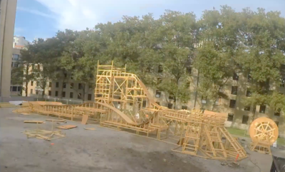
The coaster at its furthest stage of construction.
EC build has historically struggled with biting off more than it can chew and trying to do too many new things per year. Based on my experience, I would really recommend sticking to only one major new “innovation” (i.e. features that we have never successfully designed or implemented before) per year. Going into the project attempting two (the banked curve & the multi-rider cart) was inadvisable and made the project much more demanding than we could actually reasonably handle. This was compounded by the fact that it was EC’s reopening year following two years of renovations, meaning that for the entire time I was designing the project, the resources that we’re able to utilize within EC’s physical space (e.g. the makerspace) were inaccessible. Additionally, our planned project location was still a construction site that I couldn’t survey in advance of breaking ground in August. This probably should have forced me to downsize the project. However, we also learned a tremendous amount in the process of tackling the goals we set for this project, and its massive scale forced EC to become far better organized and well-managed than before. Hopefully this new knowledge and skillset will carry through for future years where we will have more resources and a larger volunteer base to work towards goals even beyond these ones.
I didn’t want to make this blogpost too long, but I have a lot more detailed documentation of this project if anyone is curious. I wrote this document with more specific tips and reflections for anyone who may be interested in becoming a project lead / designing an East Campus rollercoaster in the future. For an exhaustive timeline of every single thing that went into this project from initial conception up until we broke ground, this timeline is probably about as detailed as it gets. To view more detailed photos of the coaster during construction, check out this folder. A timelapse of both the fort and coaster’s construction can be viewed here.