Blinky Lights (Part I) by Evan B. '10
An example of how I go about building things.
And I’m back! I’m determined to make up for not posting at all in the last month by being incredibly prolific in the next. I expect this to last for maybe one post after this one. But, hey – a guy can dream, right?
I should also warn people at the beginning that this is a long post. I wrote it to show people the way that I chose to tackle an electronics problem that was presented to me. It’s not something that I learned directly from any class, and I don’t have any clever terms to describe how I approach things. But it still shows something that I’ve learned from here, because before I got to MIT, I never would have been able to make it all the way through a project like this. Those of you that know basic electronics will find parts of it boring, and those of you that don’t will find parts of it inaccessible. You should read this anyway, because it’s just a cool project.
In my advising seminar last year (6.070 – it’s a great class – I highly recommend it, not just as an advising seminar), the instructor said (and I’m paraphrasing here) that “all of electronics can be divided into blinky lights, funny sounds, and weird smells.” I’m not sure why the smells were included though – we usually try to avoid those.
I’m a little disappointed that nobody has asked me about the breadboard I’m working with in my banner photo, because that actually happens to be a prototype for the project I want to talk about. It falls into the blinky lights division.
My friend Chris ’09 and I rented a Zipcar for a day at the beginning of the summer, because he was helping me move into my summer room at EC, and he also needed to run to Target, Costco, and a few other places. And once you have a Zipcar for more than 4 or 5 hours, it becomes cheaper to get it for the whole day, so we threw in a trip to IKEA just for good measure.
While we were there, we discovered these awesome glass shelves with fluorescent lights on the inside. They were called NIANs, in IKEA’s typical we’re-going-to-pretend-to-be-exoticly-Swedish-while-still-using-words-that-sound-like-English fashion. They were also on clearance, and thus marked down from $70 to $10. Now, granted, it is IKEA, so it’s hard to tell whether it was originally $70, but regardless, at $10, that was an awesome deal, so we bought two of them each. They look something like this:

So we’re two EE-inclined guys, and we look at these lit shelves, and we come to the natural conclusion that the only possible thing to do with them is to replace the fluorescent bulb with RGB LEDs, and then make that computer controlled.
And because Chris was a lighting techie in high school, he suggests that we should make both ends communicate using DMX512, a standard protocol for communicating between stage lighting devices.
So…I have a project. Well, more of a problem (problem as in problem set, not personal problem). And the way that I solve problems like that is by breaking it down into a series of simpler problems.
But before I do that, I’d like to give a quick preview of the finished project, or at least the project as it is now. We don’t have the LEDs in shelves yet, but we do have a demo board that drives one LED:
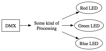
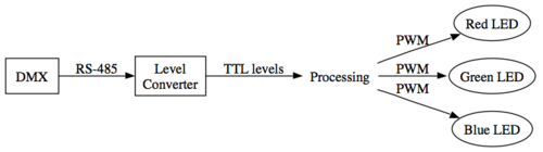
Ok. Back to the design steps. The first step for me is figuring out what the signal path is. I’ve already established that I’m using DMX to drive RGB LEDs, so it looks something like this:
Ok. The next step is to figure out exactly what’s coming in and exactly what needs to go out. On the one end, DMX travels on top of a protocol RS-485. That’s a protocol with 2 wires, and the signal is either a 1 or a 0 based on which of the two wires has a higher voltage than the other (called a differential signal).
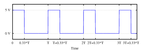
On the other end, the LEDs will be powered with a PWM signal. PWM is a way of varying a signal from completely on to completely off. Since the red, green, and blue components of the LED should each have a variable brightness, we can use PWM to change it. Basically, you turn the output on and off really quickly, and the longer it’s “on,” the brighter the LED seems, until it’s always on, which is full brightness. For those of you who are math inclined, the brightness level that our eye perceives is the average voltage over time. Here’s a photo showing what the signal looks like when it’s 1/3 of the full brightness:
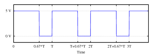
Just for comparison, here’s another signal that is 2/3 of full brightness:
Ok. So we know what signals we’re dealing with now. Let’s go ahead and summarize again:
Now that the problem is pretty well defined, I try to start from each side and work my way inwards until I have a series of processing “blocks” that I know I can implement individually.
For example, the two wires in the RS-485 (the protocol that DMX uses) signal can as high as +12V or as low as -7V, but most of the chips that I work with operate with signals that are +5V for a “1” and 0V for a “0” (These are known as “TTL logic levels”). Feeding something with the levels of RS-485 will almost immediately fry the chips, so I need to convert those levels to TTL logic levels.
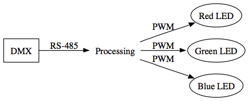
Now, it just so happens that I know of a component that can take in TTL level DMX signals and convert those to PWMs: a microcontroller (often abbreviated μC – remember that μ is the Metric abbreviation for micro). A microcontroller is sort of like a miniature computer: you can write programs for it (usually in C), download them onto the chip, and either read inputs from the pins or make the pins high or low. Their processing power is roughly equivalent (or maybe slightly better) than the earliest computer that used to take up whole rooms. Since I’ve turned the problem into TTL signals coming in, and TTL signals going out, a microcontroller can probably take the place of that void of “Processing.”
So, the final flowchart looks sort of like this:
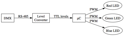
And that’s the signal path. But that’s a whole lot to digest for one post, so I think I’m going to stop there, and deal with the questions that I’m sure people have (because I’m terrible at explaining these sorts of things). Sometime soon I’ll do another post about how you go from that flowchart to a circuit, and then to an actual working PCB, and also deal with some of the problems I had – because it’s never as simple as the flowchart makes it look!
[1] (This photo was adapted from the Wikipedia article on PWM, and so I am obliged to release it under the GFDL. Therefore, I also provide the source code used to generate the images – 1 and 2)
I’m beginning to like EECS more and more !
I have a question : when you convert from DMX to TTL, don’t you loose power ? Isn’t there a way to just control it a little better, like, I don’t know I’m no specialists, by using a resistance ? (I’m not sure that’s the english word though…).Won’t it reduce the 12V ? Because transforming from DMX to TTL looks like loosing an amount of power that would have been useful.
Then again, I don’t really know a lot about electronics !
Good question! This is one of the things that I had a hard time explaining, so let me try again:
RS-485 is a differential signaling mechanism. This means that there are 2 wires. Either of those wires can have any voltage between -7V and +12V. However, the specific voltage doesn’t matter. All that matters is that one of the wires has to have a higher voltage than the other. So you could have one wire at -7V and one at -6V, or one at -5V and one at 0V, and this would still be a valid signal.
In part II I’ll talk about how to deal with that and turn it into a TTL-level signal.
Any sort of processing does cost a little power, but the way that most devices work now, the power cost isn’t that significant.
Um, should have guessed. I now hear in my head last year physics teacher telling us delta E is almost equal to zero…
I hope part II will come soon ! I want to learn more ! It’s making me think about my original decision to study nanotechnology…this looks so practical !
Remember the disco floor ? Does it work the same way ? Or it’s totally not the same thing ?
Ok I’m really sorry for the double post, but something just hit me : you said the programs would be written in C (yay!). I thought Python or scheme was mainly used ?
Sorry again for double post !
Do you ever use Java or C++? I am considering becoming an EECS major as well, although more cs then EE…. I am really proficient in Java, and I sort of know C/C++. Which is more useful at MIT?
Two of the people who built the Disco Dance Floor are friends of mine, actually. Although both of our designs do similar things, we do it in different ways. There’s is designed to drive dozens of LEDs individually, while I’m trying to drive about 10 LEDs the same (i.e. they’re all the same color). We do have in common the idea of using PWMs to regulate the brightness, though – that’s a very commonly used concept. Any time you see something with variable brightness, there’s a pretty good chance it’s being PWMed.
As for languages, Python and Scheme are commonly used in computer science research, because you can do some very theoretical abstractions with them. Microcontrollers, though, aren’t nearly as fast as computers (for this project in particular, I’m only running mine at 8 Megahertz), you need as much processing power you can get, and you can’t afford to use as many abstractions. C lets you work at a lower level, which in turn results in more efficient code. In fact, some microcontrollers are still programmed in assembly (machine code), although that’s becoming more and more rare.
@Pascale
I wouldn’t say that any language in particular is more useful; generally classes that are programming-oriented involve making sure you know the language. I can’t think of any CS classes that use C++. Most of them use Python, Scheme, Java, uh…yeah. That’s about all I can come up with off the top of my head. That doesn’t mean that other languages are useless, though. It’s just that certain langauges have certain properties that make them useful for teaching certain things.
Well, I hope we will see the result soon !
I should learn how to put on paper a problem, you’re really good at his!
This is so cool, taking what you learned to create something cool and know in the back of your head : I did it ! If I get in, i want one ! Or, how about, I’ll make one ! With you as my mentor of course ^^ .
I have to admit that I would never come up with using time to regulate brightness, I would have probably used D/A converters or something so, I’d use 2 registrys: a shift registry as a buffer and a parallel registry to generate the actual output signal which is then converted to analog and powers the LEDs. btw we use AT89C2051 (8051 processor) at school, and we program them in assembly
  but that’s purely for educational purposes.
Yay! A post!
Just be careful where you put (or wear) those lights..
everyone knows that LEDs=bombs.
Hey, guys –
While I’m sure Star and anyone else involved appreciates the implicit support, that’s something that I’d rather not talk about, at least on a space this public.
If any of you have opinions or questions, e-mail me, and I’d be glad to share what I know (which isn’t much) and think (which is quite a bit).
I had an idea of making RGB LED sign for our robotics team as a fun side projects for the new members and then add in some micro controllers to make the LEDs change color, flash, dim etc with preprogrammed patterns. That is like soldering practice, programming practice and cool end product all at the same time.
However, I realized that finding a suitable power source(and designing a simple, efficient circuit for 3 separated numbers) for the 40+ LEDs might be a problem, because we would like to be able to hold it up for fun at the competitions for most of the day or so.
Thus… we are resorting to etching PC Board dog tags again and maybe add on a led or so.
Any ideas for good powering source?
I wish my school had robotics or micro electronics classes too!
For robotics, we have to do everything after school in a freezing cold car garage (8PM-12AM during build seasons everyday-ish and 10am to midnight, occasionally all-nighters, on the last few days. Using sharp objects when one is sleepy is NOT SAFE!) and somehow fund raise $20,000 a year for the competitions and materials. So, opportunities don’t always come on a silver platter; You have make it happen. ; )
Hi Evan! What other cool things have you made at MIT? You should consider posting some pictures on the
“part 2”. And do the EE or MechE classes allow students to use their creativity to design and make their ‘homework’?
Yay, EECS stuff! I know nothing about electronics, but I did know about PWM. Yay, signals… =)
Cool post, Evan. I love hearing about EECS, but give us a post about the AI class you’re in – I’m so much more into the CS side of things, and AI is just amazing.
I’m jealous!
What I mean is that while I am a pretty good programmer and have enough knowledge to understand everything you talked about here (thanks to Physics, a (mostly a waste of time) semester EE class, and my Computer Architecture class), I don’t have enough knowledge of the components or circuit design to make such a thing. I really love the theoretical computer science side of things, but I also really want to get a better knowledge of the EE side of things, hence why if I get into MIT I’m probably headed toward a 6-2 path.
Anyway, did I have a point? Not really… but … Awesome project idea. I look forward to seeing how they turn out.
~Donald
So wish we had a micro-electronics class in my school….sigh! Robotics competitions are unheard of here. Do you think its possible that I could do some useful background research on my own?…Can you suggest any course of action that would quench my thirst to learn fundamental robotics?
Amazingly enough, I actually understood that.
Evan, kudos to you on breaking your Course 6 lingo down into something that’s more-or-less understandable to us normal folk. :D
Yeah! I actually thought about “making it happen” too. I just wanted to know how I could first come to par with the technical know-how required.
But I do plan to hold the first ever robotics exhibition in my school anyway. Though Im a wee bit skeptical of its success, considering the fact that hardly any other students share my enthusiasm for robotics out here. Lets see…
What is the difference between a physicist, an engineer, and a mathematician?
If an engineer walks into a room and sees a fire in the middle and a bucket of water in the corner, he takes the bucket of water and pours it on the fire and puts it out.
If a physicist walks into a room and sees a fire in the middle and a bucket of water in the corner, he takes the bucket of water and pours it eloquently around the fire and lets the fire put itself out.
If a mathematician walks into a room and sees a fire in the middle and a bucket of water in the corner, he convinces himself there is a solution and leaves.
I’m more of a Course 7 type person than a Course 6 type person, but your entry was intersting regardless, Evan. (Even though I’ll admit that I didn’t always know what you were talking about! )
)
*Okay, I meant interesting there.
Some has all ready done most of the work for this…
Go here: http://www.hackaday.com/2007/09/28/fnordlicht-rgb-mixing-led-light/
and click the read link
It is a RGB light controlled via RS-485, with atmel Atmega8.
With a little modification to the circuit(s) and code this could be rapid prototyped in about 1/2 a day.
And to make look real slick you could use Zigbee modules to control them and some sort of interchangeable Li-Po/Li-ion battery setup with a high efficiency switcher to power it. It’ll look like a normal shelve.
I’m like the smartest 14 y/o in G-vegas