
Samantha: The Automated Nerf Gun Turret by Cami M. '23
a personal project by raymond t. '23
Back in January 2021, my boyfriend Raymond realized he was bored during MIT’s IAP01 IAP is Independent Activities Period. Essentially, MIT students get the month of January off to do whatever we please. period and decided he wanted to make an automated nerf turret.
Here is how that went.
Note: A lot of this information is taken directly from Raymond’s website and you can find the original post here.
Part 1: Mechanical
Raymond took 15.S20 Design for 3D Printing as his first foray into CAD.02 Computer Aided Design
When initially designing the model, Raymond knew he wanted a turntable for easily maneuvering the left and right axis. Then, he quickly realized that he needed arms on the side to move the gun up and down. It’s a relatively large gun so he wanted something very stable. He used Lazy Susan turntables as an inspiration since it would be easy to mount on the gun since the gun required a lot of torque due to its size.
The Nerf Gun
In order for this to work, Raymond had to get a hold of a fully automated, fully electronic nerf gun. He ended up choosing the Nerf CS-18 N-Strike Elite Rapidstrike. They were pretty hard to come by in Boston so Raymond ended up buying one off of Facebook Marketplace.
Once he acquired the gun, he began to take it apart. He snipped the wires to the motor and then ran longer wires out of the gun that could connect to the motors. There were two motors inside of it, a pusher motor that pushes the next dart in and the flywheel that shoots the dart out at a rapid speed.
Now that he knew the look, make, and feel of the gun, he could start CADing the turret casing.
The Base
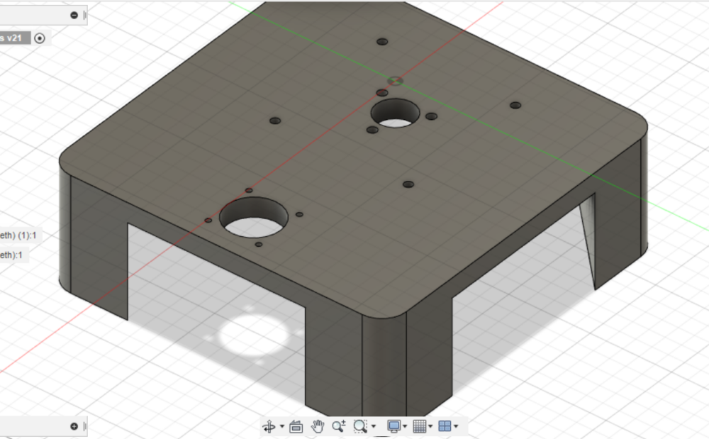
The base consists of two large holes surrounded by mounting holes: one for the stepper motor03 From wikipedia: A <em>stepper motor</em>, also known as <em>step motor</em> or <em>stepping motor</em>, is a brushless DC electric motor that divides a full rotation into a number of equal steps. and the other for the wires from the main assembly. The smaller hole has the 4 mounting hole for the lazy susan in addition to 3 holes arranged in a triangle. The three holes were supposed to be for a slip ring (more on this later).
The Gears

On top of this base is a set of gears wihch provides more torque from the stepper motor through a 5:1 gear reduction. This ends up being quite important since the top half is almost 4lbs heavy.
The Walls
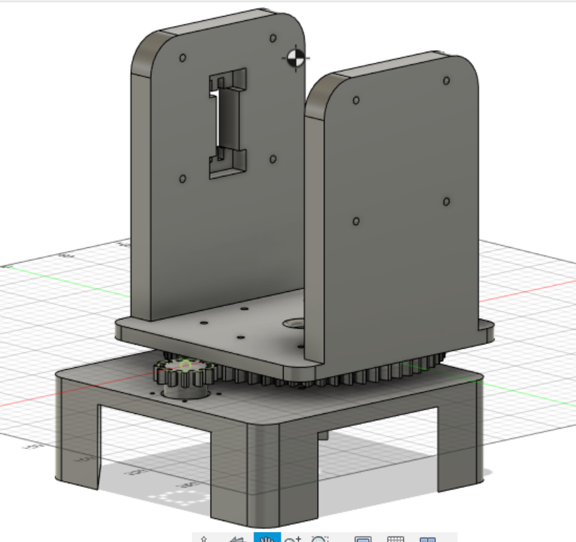
Mounted on the gears are the walls which are used to hold the nerf gun up. The left wall has a slot cut out from it to mount the servo04 from wikipedia: A servomotor is a rotary actuator or linear actuator that allows for precise control of angular or linear position, velocity and acceleration which controls the angle of the nerf gun.
The Gun Mount
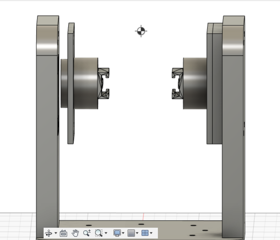
Mounted on the walls of the set of lazy susans is the gun mount. The Nerf Gun has a tactical rail system so Raymond printed the railing onto some cylinders. The left mount is slightly extended to interface with the servo on the wall.
The Overall Turret
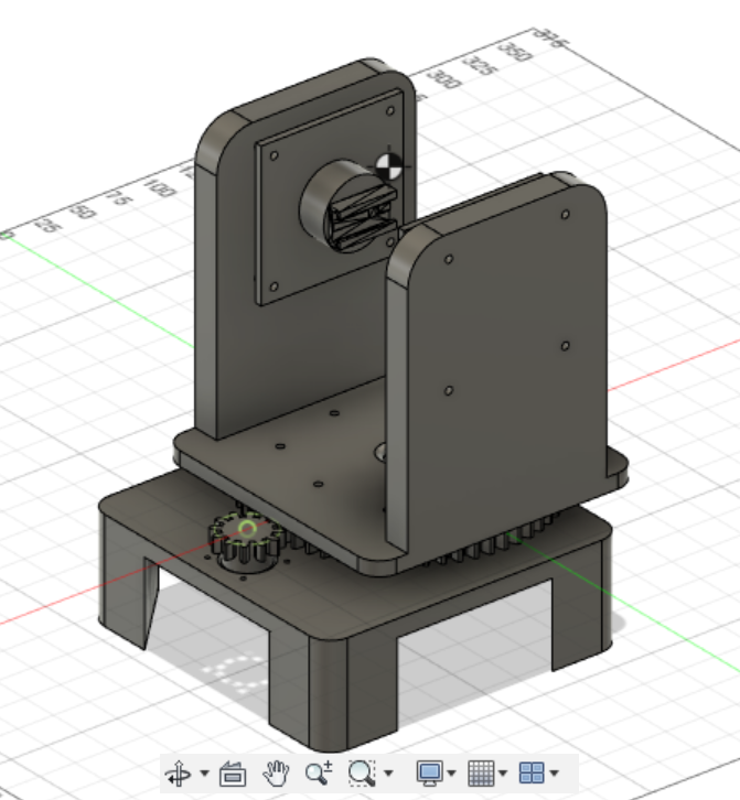
This is the final product.
Part 2: Electrical
The turret uses an Arduino Nano hooked up to a stepper motor driver (for the gears), the servo, and two relays05 An electormagnetic that, when on, completes a different circuit. It is an electromechanical switch. for the flywheel and the pusher on the nerf gun.
Initially, Raymond planned to use a slip ring to pass through the center of the turret so that it could turn 360 degrees continuously. However, there was too much noise in the slip ring to transfer USB 2.0 webcam data through. As a result, he had to remove the slip ring so after a few revolutions, the turret will twist itself up but this is a pretty rare situation.
Part 3: Software
Now that we have the turret casing and everything hooked up, it was time to program the turret! In simple terms, the arduino will receive control signals over serial from a computer vision script from Raymond’s laptop.
Arduino-side
The arduino code is somewhat simple; it decodes characters over serial and applies the given command to the motors. It is short enough to be displayed here in its entirety:
// Include the AccelStepper library:
#include
#include
// Define stepper motor connections and motor interface type.
// Motor interface type must be set to 1 when using a driver:
#define dirPin 2
#define stepPin 3
#define flywheelPin 4
#define pusherPin 5
#define motorInterfaceType 1
#define servoPin 8
// Create a new instance of the AccelStepper class:
AccelStepper stepper = AccelStepper(motorInterfaceType, stepPin, dirPin);
Servo servo;
bool usingRunSpeed = false;
void setup() {
  Serial.begin(9600);
  pinMode(flywheelPin, OUTPUT);
  pinMode(pusherPin, OUTPUT);
  // Set the maximum speed and acceleration:
  stepper.setMaxSpeed(10000);
  stepper.setAcceleration(3000);
  servo.attach(servoPin);
  servo.write(110);
}
void loop() {
  if (Serial.available() > 0) {
    String in = Serial.readStringUntil('\n');
    switch(in.charAt(0)) {
      //runspeed?
      case 'm':
        usingRunSpeed = true;
        break;
      case 'M':
        usingRunSpeed = false;
        break;
      //stepper
      case 's':
      {
        float newSpeed = in.substring(1).toFloat();
        stepper.setSpeed(newSpeed);
        Serial.println("Stepper speed set");
      }
        break;
      // stepper to position
      case 'T':
      {
        float absolutePos = in.substring(1).toFloat();
        stepper.moveTo(absolutePos);
        Serial.println("Stepper pos set");
      }
        break;
      //Servo
      case 'S':
      {
        float newAngle = in.substring(1).toInt();
        servo.write(newAngle);
        Serial.println("Servo angle set");
      }
        break;
      case 'F':
        digitalWrite(flywheelPin, HIGH);
        Serial.println("Flywheel pin set high");
        break;
      case 'f':
        digitalWrite(flywheelPin, LOW);
        Serial.println("Flywheel pin set low");
        break;
      case 'P':
        digitalWrite(pusherPin, HIGH);
        Serial.println("Pusher pin set high");
        break;
      case 'p':
        digitalWrite(pusherPin, LOW);
        Serial.println("Pusher pin set low");
        break;
      default:
        Serial.println("unknown command");
    }
  }
  if (usingRunSpeed){
    stepper.runSpeed();
  } else {
    stepper.run();
  }
}
Computer-Side
Initial Movements
Before Raymond hooked up the webcam to the nerf turret, he wanted to ensure that the movement was smooth and actually worked so he wrote a small Python script to map mouse movements to the turret’s movement.
We have a series of videos documenting this process:
At this point we were just messing around and testing it. You’ll see from the video below that it fires pretty quickly.
With the Webcam
After ensuring that she could move and shoot, Raymond finally hooked up the webcam. Raymond used the python API available from OpenPose to detect people in the camera frame. The system uses the PID controller to manipulate the stepper motor and server motor to keep the center of the camera aligned with the center of mass of the person.
Here is the code for the camera loop:
while True:
    if not video_capture.isOpened():
        print("Unable to load camera")
        sleep(5)
        pass
    ret, frame = video_capture.read()

    # Process frame
    datum = op.Datum()
    datum.cvInputData = frame
    opWrapper.emplaceAndPop(op.VectorDatum([datum]))
    output_frame = datum.cvOutputData[:,:,:]
    if datum.poseKeypoints is not None:
        if datum.poseKeypoints[0][1][2] > 0:
            neck_x, neck_y, neck_score = datum.poseKeypoints[0][1]
            if abs(neck_x - WIDTH/2) < ATTACK_MARGIN and abs(neck_y - HEIGHT/2) < ATTACK_MARGIN: set_flywheel_on() if first_lock_time is None: first_lock_time = datetime.datetime.now() if (datetime.datetime.now() - first_lock_time > datetime.timedelta(seconds = 0.3)):
                    set_pusher_on()
                    if not pygame.mixer.music.get_busy():
                        pygame.mixer.music.play()

                    cv2.circle(output_frame, (int(neck_x), int(neck_y)), 20, (0, 0, 255), -1)
                else:
                    cv2.circle(output_frame, (int(neck_x), int(neck_y)), 20, (255, 0, 0), -1)
            else:
                first_lock_time = None
                cv2.circle(output_frame, (int(neck_x), int(neck_y)), 20, (0, 255, 0), -1)

                set_flywheel_off()
                set_pusher_off()
            new_speed = stepper_pid(neck_x)
            if abs(new_speed) < 100: new_speed = 0 set_stepper_speed(new_speed) # Servo new_angle_delta = servo_pid(neck_y) angle += new_angle_delta angle = max(100, angle) angle = min(140, angle) set_servo_angle(angle) else: first_lock_time = None set_pusher_off() set_flywheel_off() nonzero = datum.poseKeypoints[0, :, 2] > 0
            nonzero_keypoints = datum.poseKeypoints[0, nonzero, :]
            if nonzero_keypoints.any():
                x, y, a = nonzero_keypoints[0]
                new_speed = stepper_pid(x)
                if abs(new_speed) < 100:
                    new_speed = 0
                set_stepper_speed(x)
    else:
        first_lock_time = None
        set_pusher_off()
        set_flywheel_off()

    ...
Here are some videos of the initial camera tests.
At one point Raymond made it so that whenever the nerf gun fired, it played a sound clip of Emma screaming. You can see and hear that here.
Essentially the camera will look around and lock onto a body. After it gets a good lock (about 0.3 seconds) it will then fire.
Part 4: The Final Product
Here are some successful videos of the nerf turret doing its thing.
Raymond ended up submitting this project to a hackathon hosted by Theta Delta Chi and he ended up winning first place and he won a PS5. Which was really cool.
You can see that Instagram post here.
- IAP is Independent Activities Period. Essentially, MIT students get the month of January off to do whatever we please. back to text ↑
- Computer Aided Design back to text ↑
- From wikipedia: A stepper motor, also known as step motor or stepping motor, is a brushless DC electric motor that divides a full rotation into a number of equal steps. back to text ↑
- from wikipedia: A servomotor is a rotary actuator or linear actuator that allows for precise control of angular or linear position, velocity and acceleration back to text ↑
- An electormagnetic that, when on, completes a different circuit. It is an electromechanical switch. back to text ↑