
Shiny Circuits by Kim D. '09
Shiny, in some subcultures at MIT, means REALLY AWESOME
Hey guys! I know it’s been a little while since I have blogged. The problem is that people like pictures. And people like to know about the lives of MIT students. BUT, right now even though I have both pictures and the life of an MIT student, my pictures are not about my life as an MIT student (they tend to be about how neat trees look right after rain in the Fall). That’s because most of the things I’m doing now as an MIT student (researching at a Department of Defense Research and Development Laboratory, observing in a local high school classroom, interviewing for cool jobs) expressly forbid taking pictures.
So, I decided to take pictures of part of someone else’s life at MIT: 6.131 Lab.
6.131 Lab, or Power Electronics is one of those classes that reminds students why they came to MIT in the first place. At this time of year in many other classes, students are cramming as much into their heads as possible for midterms. At this time of the year in 6.131, students have just finished working late nights to create a system that lets them drive a go-cart. Now they’re working on controlling fluorescent lights.
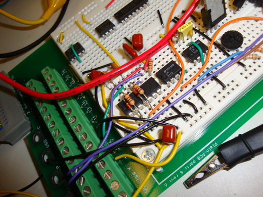
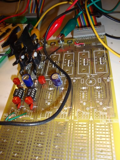
Breadboard by Noah S. ’10
Why, you might ask, does a fluorescent light need to be controlled? You have likely seen a demonstration of how easy it is to wire up an incandescent bulb; you basically just connect it to a battery. In these more traditional bulbs, the filament is a resistive unit, so the more voltage you put across it, the more current will flow through, and the brighter it will shine. The filament is made out of metal (these days, usually Tungsten), so even though there is some resistance there, it is not very high.
In a fluorescent light, instead of a wire filament, there is a tube filled with low-pressure mercury vapor. When the light is turned off, this gas provides a very high resistance. Even though mercury is metal just like Tungsten is, it’s spread out as a gas. For electric current to flow through the bulb, it needs to be able to jump from one atom of metal to the next, all the way to the end of the bulb.
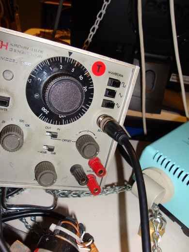
Signal Generator in Power Electronics Lab at MIT
So that’s the first difference: to get the light going in the first place, you need to provide a HUGE voltage. So why aren’t fluorescent bulbs just like incandescents with bigger batteries? Well, as soon as you have started the flow of electrons through the tube, the vapor ionizes! This means that its resistance drops very suddenly. If you continued to use the same amount of voltage you used to start the lamp to run it, it would explode!
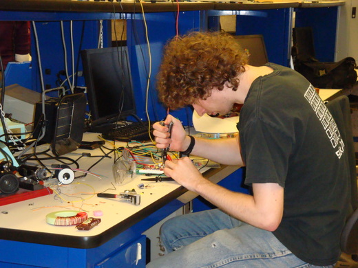
Noah S. ’10 — Hard at work. See the giant green donut-thing with red wire? That’s a huge inductor.
And then the final kicker: The V-I characteristics, or relationships between voltage and current, for the lamp, are really weird. Even if you put a high amount of voltage in to start the lamp, then bring it down to the perfect level, it is a very fragile system. If some tiny little variable changes, like the temperature, it could become unstable, the current could run away, and it would still break! *For 6.131 Professor Leeb’s explanation of why this happens, see note at the end.
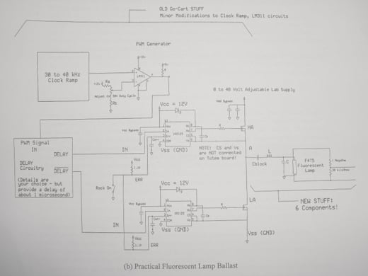
The answer to all of our problems!
So, the answer, clearly, is to use the circuity represented above. All clear? Just in case it’s not, let’s explain…
So, the goal is to provide a big initial voltage, then turn it down and set up some sort of self-policing system.
Most of the things in the picture above are just made to generate a huge square wave (40 Volts). There’s a part where you can adjust the Duty Cycle, or what part of the time the square wave is high or low. The other really important parts are right next to the part labeled ‘Fluorescent Lamp.’ They are ‘L’ and ‘C.’ The huge square wave comes in through L (an inductor) and then chooses whether to go through the C (capacitor) or lamp. If the lamp is off, it goes through the C, since there’s so much resistance in the lamp. If the lamp is on, it goes through the lamp and mostly avoids the capacitor.
When the lamp is off, the inductor and capacitor form a resonant circuit. If the frequency of the square wave going in is right, the voltage in the capacitor voltage builds up until it is high enough that the lamp starts. Once the lamp starts, the inductor helps to keep the amount of current in the lamp steady.
Other cool things about the lab are winding the big inductors yourself, doing all your own soldering, and working with chips that are getting hot enough that they need huge heat sinks (the big black metal things in the photo below.) Let me know if you have any questions about 6.131 or lab classes in general. And thanks to Noah S. ’10 for showing me his circuitry and giving me a refresher course on building a lamp ballast :)
Totem board, Noah S. ’10
*I’m going to quote Professor Leeb himself here, because he explains it so clearly.
In the lit fluorescent lamp, “an increase in terminal voltage corresponds to a decrease in terminal current, and vice-versa. This happens because, roughly, as the current decreases in the tube, the number of charged carriers in the tube also decreases, decreasing the conductivity of the plasma column in the tube. So a higher voltage is needed to maintain the lower current! Increasing the current on the other hand, increases the conductivity of the plasma. A lower voltage is required in this case to sustain the higher current.
With these properties, “imagine a slight, inevitable disturbance that momentarily increases the current in the bulb. This disturbance could be a slight change in exterior temperature, for example. The voltage across the tube remains fixed, but now we are “off” the equilibrium curve, with a larger number of charge carriers in the tube compared to before the disturbance. Off the equilibrium curve, this voltage will push yet more current into the bulb, further increasing the conductivity. If the voltage remains unchanged, the bulb enters a “runaway” condition, where the current increases until something breaks.”
hey!! Cool pictures.. and great post..
I want to do my Electrical Engineering from MIT.. thanks for the inspiration..
and yeah!! I am FIRST!!
Nice pics!
I love posts like this.
That is so cool. I’m definetely taking all the electrical engineering courses I can.
I live in S√£o Paulo, and though it is a great center of electronic products, there is only one place I can buy components, and it is hard and expensive to find certain ICs.
It will be so great to learn and have components available. I feel like I could build anything. : )
I loved that :D That’s all I just loved that…
I never took 6.131 but I enjoyed 6.115… except when I spent too much time debugging.
So…the signal generators are actually CHAINED and PADLOCKED. Hardcore.
So yeah… In college(I’m hoping for MIT!), I definitely need to take some electronics courses. This stuff is so interesting!
So to counteract positive feedback we need a complicated setup like in that diagram… I love our universe. It’s so interesting.
wow! best blog post ever!
^
+1
I’m doing nearly the same thing in my high school engineering class! How cool!
Uwaaaah, looks interesting, but I always despised circuit diagrams in Physics, I guess that’s why I prefer to do Comp. Sci. Or English. Or Music. Still, that looks awesome!